DK-811928 Instructions

Note: These parts and instructions also apply to kits DK-812928, DK-813928, and DK-814928. The only difference is the part numbers, which will match your specific SKU.
Parts Included
1. Raise the vehicle and prepare for installation
a. Safely support the vehicle.
b. Remove the front wheels.

2. Remove the skid plate and the sway bar
a. Remove the skid plate.
b. Remove the skid plate brackets.
c. Disconnect the sway bar link from knuckle by removing the link hardware.
d. Remove the sway bar bracket from the chassis.
e. Remove the sway bar.

3. Remove the brake lines and the caliper
a. Disconnect the brake line at the chassis.
b. Remove the brake line junction from the hard line to the brake caliper soft line.
c. Disconnect the brake line and bracket at the knuckle.
d. Remove the brake caliper bolts and the caliper assembly.
e. Remove the brake rotor.

4. Remove the tie rod and the ABS lines
a. Remove the cotter pin and the castle nut from the tie rod at the knuckle.
b. Separate the tie rod from the knuckle using a ball joint puller.
c. Disconnect the wheel speed sensor from the knuckle.
d. Remove the lines from the upper control arm.

5. Remove the upper control arm and the steering knuckle
a. On 4WD models, remove the hub center cap. Then remove the cotter pin and the axle retaining nut.
b. Remove the ball joint cotter pin and the castle nut at knuckle. Separate them by using a ball joint puller.
c. Remove the steering knuckle lower ball joint attachment bolts.
d. Remove the knuckle.
e. Remove the upper control arm pivot bolt.
f. Remove the upper control arm.

6. Remove the shocks, axle, and the lower control arm
a. Remove the axle assembly (4WD models only).
b. Remove the upper and lower shock hardware.
c. Remove the shock.
d. Loosen and remove the outer tie rod.
e. Remove the lower control arm alignment hardware. Note the direction of the hardware as you will reinstall the hardware in the same way it was removed.
f. Remove the lower control arm.

7. Axle Assembly (4WD Only)
a. NOTE: The following steps will cover machining and building your own axle assemblies using Dirt King axle shafts. This is an alternative option to purchasing complete axle assemblies. Thoroughly review the instructions to ensure you have the necessary proficiency and the required tools to complete the steps properly.
b. Disassemble the factory axle assembly after removing it from the vehicle.
c. Use a press to properly separate the outer CV from the axle shaft.
d. Machine the inner CV housing to a 22° taper at internal edges, as shown in the reference image marked in red. This tapering accommodates additional CV down travel. If machining tools are unavailable, you can send your CV housings to Dirt King for machining.
e. Replace the old CV boots with new ones during axle reassembly.
f. Apply Permatex 84107 epoxy to each mating surface of the CV boots to secure them, as increased CV articulation may cause the boots to detach during use.
g. Install a 1-inch differential drop when using the long-travel suspension system.

8. Install the Dirt King +2 kit
a. Install the new Dirt King lower control arm using the OEM alignment hardware: be sure to reinstall the hardware in the same direction it was removed.
b. Torque the lower control arm alignment hardware to OEM spec: 135 ft lbs.
c. Install the new spec shock. Torque lower bolts to factory specifications of 85 ft lb. Torque upper coil bucket bolts according to your shock manufacturer's instructions.
d. Install the lower ball joint attachment to the lower control arm.
e. Install the new Dirt King axle (4WD models only).
f. Install the steering knuckle to the lower ball joint attachment with the provided spindle spacers between the steering knuckle and the lower ball joint attachment. Torque to 118 ft lbs.
g. Install the upper control arm using the OEM rear pivot bolt. Install the large washers to the outside of the bushings. Torque to 85 ft lbs. If you are using a double shear kit, place the washers to the outside of the double shear kit.
h. Install the upper control arm ball joint to the steering knuckle. Torque the castle nut to 85 ft lbs. Install the cotter pin.

9. Install tie rod extension
a. Apply thread locker to the tie rod extension male threads and tighten it to the outer tie rod. Apply anti-seize to the female threads of the tie rod extension and install to the inner tie rod. Torque jam nut to 41 ft lbs.
b. Torque the lower control arm ball joint castle nut to 108 ft lbs. Continue to tighten the castle nut until the threaded pin is exposed on the castle nut slot and install the cotter pin.
c. Install the tie rod end to the steering knuckle. Torque castle nut to 67 ft lbs. Continue to tighten the castle nut until the threaded pin is exposed on the castle nut slot and Install the cotter pin.

10. Install the hub and the brake assembly
a. On 4WD models, install the hub nut and torque to OEM spec: 203 ft lbs. Install the lock ring and the cotter pin.
b. Install the brake rotor.
c. Install the brake caliper. Torque the mounting bolts to OEM spec: 91 ft lbs.

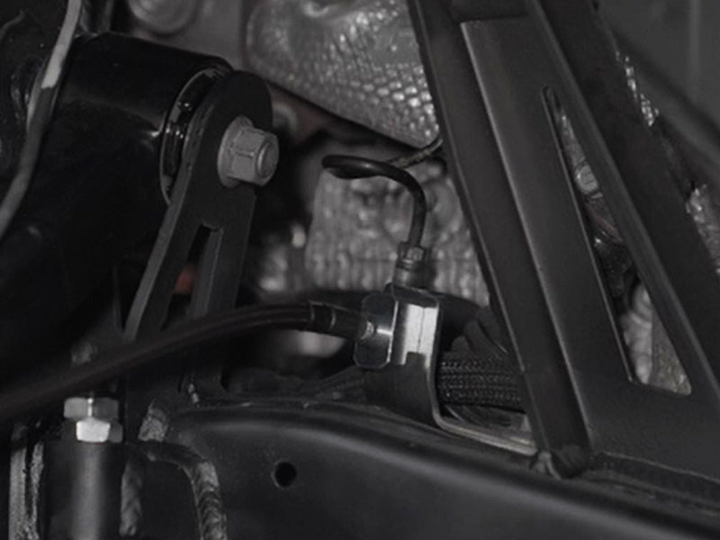
11. Install the limit strap
a. Install the limit strap to the lower control arm. Install the clevis to the other end of strap. Threads of the clevis should be approx. 3/4 towards bottom of the sleeve. This will allow strap to pull up when adjusted and tightened.
b. With the suspension drooped out, locate the limit strap tab onto the chassis. Strap, tabs, and clevis should all be in line when locating onto the chassis: do not install it at an angle (see image) Mark the chassis where the mount wil be welded and clean the chassis to bare metal for welding.
c. Cover any exposed areas that can be damaged due to welding heat or spatter.
d. Ground the welder to the clevis. Mount and tack it to the chassis.
e. Fully weld the clevis mount. Allow it to cool and then apply paint.
f. Torque the limit strap tab hardware at the lower control arm to 90 ft lbs.
g. Set the limit strap to limit full shock extension between 1/4” to 1/2”. Tighten both jam nuts on clevis.

12. Install brake lines
a. Attach the brake caliper hard line to the new soft brake line at the knuckle union. Insert the brake line clip that locks it in place to the bracket.
b. Install the brake line block at the chassis. Attach with the brake line clip. Attach the factory brake hard line to the block and tighten lines.
c. Secure the soft line and the ABS lines to the upper control arm using zip ties.
13. Review your work and repeat steps on the other side of vehicle
a. Confirm everything is installed correctly. Ensure the control arm is not contacting the shock reservoir hose.
b. Bleed the brake system per your manufacturer’s service manual.
c. Replace any lost front differentail fluid when axles were removed (4WD models only).
14. Reinstall the wheels and align the vehicle
a. Have the vehicle aligned at a qualified shop. If your vehicle is equipped with Advanced Driver Assistance Systems (ADAS), ensure it is recalibrated.

For warnings and disclaimers, visit Dirt King Disclaimer.